
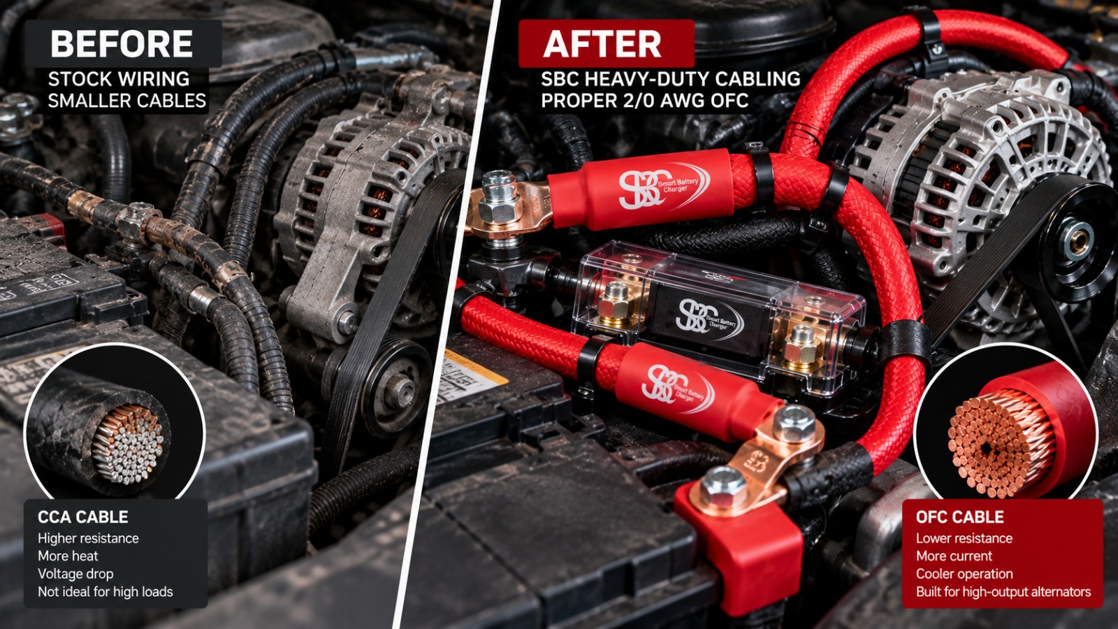
Choosing the Right 12V and 24V Cable Size for High-Output Alternators
Upgrading to a high-output alternator can provide the additional electrical power needed for winches, auxiliary batteries, lighting, compressors and other vehicle accessories. However, the alternator is only one part of the charging system. The cables connecting it to the battery and electrical loads must also be sized correctly.
Undersized wiring can cause excessive voltage drop, overheating, slow battery charging and unreliable accessory performance. These problems become particularly important in 12V systems, where even a relatively small voltage loss can affect equipment operation.
Choosing the correct cable requires more than matching a wire gauge to an alternator’s advertised amperage. You must consider the current flowing through the circuit, the total cable length, the conductor material, the insulation temperature rating and the intended voltage-drop limit.
This guide explains how to use a 12V wire size chart, understand the differences between 12V and 24V wiring, calculate voltage drop and plan wiring upgrades for high-output alternators.
12V and 24V DC Wire Sizing Chart
The table below provides a preliminary reference for selecting cable sizes according to current and circuit length. It is intended for initial planning, not as a substitute for a complete electrical calculation.
| Current | Up to 3 ft | Up to 7 ft | Up to 10 ft | Up to 15 ft | Up to 20 ft |
|---|---|---|---|---|---|
| 50A | 8 AWG | 6 AWG | 4 AWG | 2 AWG | 1 AWG |
| 100A | 4 AWG | 2 AWG | 1 AWG | 1/0 AWG | 2/0 AWG |
| 150A | 2 AWG | 1 AWG | 1/0 AWG | 2/0 AWG | 3/0 AWG |
| 200A | 1 AWG | 1/0 AWG | 2/0 AWG | 3/0 AWG | 4/0 AWG |
| 250A | 1/0 AWG | 2/0 AWG | 3/0 AWG | 4/0 AWG | Multiple conductors may be required |
| 300A | 2/0 AWG | 3/0 AWG | 4/0 AWG | Multiple conductors may be required | Multiple conductors may be required |
| 350A | 2/0 AWG | 4/0 AWG | 4/0 AWG | Multiple conductors may be required | Multiple conductors may be required |
| 400A | 3/0 AWG | 4/0 AWG | Multiple conductors may be required | Multiple conductors may be required | Multiple conductors may be required |
Important: These are preliminary sizing references, not universally validated cable ratings. Actual cable requirements depend on conductor material, insulation, ambient temperature, installation method, acceptable voltage drop and the cable manufacturer’s specifications. Before installation, verify that the selected cable can safely carry the expected continuous current.
For 24V systems, the same electrical power generally requires half the current compared with a 12V system. This can allow a smaller conductor for the same power and cable length, provided all other design requirements remain satisfied.
Why Voltage Drop Matters in a 12V System
Voltage drop occurs when electrical current passes through the resistance of a cable, connector or other part of a circuit. The longer the cable and the higher the current, the more important this resistance becomes.
For example, a charging circuit operating at 14.4V that loses 0.6V delivers only 13.8V at the receiving end. Whether that difference affects charging performance depends on the battery chemistry, charging requirements and operating conditions.
Voltage drop can also affect accessories. Electric fans, pumps, compressors and other equipment may perform poorly if the voltage at their terminals falls below the required operating range.
The basic relationship is described by Ohm’s law:
Voltage drop (Vd) = Current (I) × Resistance (R)
To reduce voltage drop, you can use a larger conductor, shorten the cable run, improve connections or reduce the current carried by the circuit.
A commonly used design target for many automotive circuits is a voltage drop of around 3%, although the appropriate limit depends on the circuit and equipment. Sensitive charging circuits may require a stricter target.
How to Calculate the Correct Wire Size
Selecting a cable involves two separate checks: voltage drop and current-carrying capacity.
1. Determine the maximum current
Start with the expected continuous current rather than relying only on the alternator’s maximum advertised output.
Consider the electrical loads that may operate simultaneously, including:
- Vehicle electrical systems
- Electric cooling fans
- Winches and compressors
- Auxiliary battery charging
- Lighting and other aftermarket accessories
The actual current flowing through an individual cable depends on the circuit layout and how the equipment is connected.
2. Measure the complete circuit length
One of the most common sizing mistakes is measuring only the positive cable.
In a two-wire system, current travels through the positive conductor and returns through the negative conductor. Both lengths contribute to the total circuit resistance.
For example, if the positive cable is 8 feet long and the negative cable is also 8 feet long, the total conductor length is 16 feet.
In vehicles that use the chassis as the return path, the calculation must account for the resistance of the chassis, engine connections, grounding points and any additional cable sections. A dedicated ground cable may be appropriate for high-current installations.
3. Set the allowable voltage drop
For a 12V nominal system, a 3% voltage-drop target corresponds to approximately 0.36V when calculated against 12V.
For a 24V nominal system, the equivalent 3% target is approximately 0.72V.
These figures are calculation targets, not guarantees that every device will operate correctly at the resulting voltage. Always check the requirements of the connected equipment.
4. Verify cable ampacity
A cable may meet the voltage-drop target but still be unsuitable for the current because of its insulation rating, installation conditions or temperature exposure.
Check the manufacturer’s continuous current rating and applicable derating guidance. If the voltage-drop calculation and ampacity check require different sizes, select a cable that satisfies both requirements.
When the calculated size falls between available options, the larger suitable conductor is generally the safer starting point, subject to terminal compatibility and installation constraints.
The Big Three Wiring Upgrade
When installing a high-output alternator, the factory wiring may not be suitable for the revised charging capacity. The alternator’s output cable and the vehicle’s grounding paths should be assessed as part of the upgrade.
The Big Three wiring upgrade refers to improving three main connections:
- Alternator positive to battery positive: Provides a suitable charging-current path between the alternator and battery.
- Engine block to chassis ground: Improves the return path between the engine and vehicle chassis.
- Battery negative to chassis ground: Provides a suitable connection between the battery negative terminal and chassis.
The correct conductor size must be selected for each connection based on its current, length, routing and installation conditions. Do not assume the original factory cables can safely handle the additional current simply because the alternator physically fits the vehicle.
Connections should use suitable terminals, clean contact surfaces and secure fastening. After installation, verify voltage drop under load and inspect for abnormal heating.
Engine Bay Temperature and Cable Selection
A cable’s performance depends on more than its gauge. The temperature rating of its insulation and the environment in which it is installed are also important.
Engine compartments can expose wiring to heat from exhaust components, turbochargers, radiators and other equipment. Higher conductor temperatures increase electrical resistance, while excessive heat can damage insulation over time.
Common automotive cable types include:
- PVC-insulated cable: Suitable only where its temperature and environmental ratings meet the installation requirements.
- TXL or SGX cable: Common automotive options with insulation designed for demanding vehicle environments. Confirm the exact rating of the selected cable.
- High-temperature silicone cable: Available for applications that require suitable temperature resistance and flexibility.
Do not choose cable solely because it is described as heavy-duty or high-temperature. Check its actual specification, current rating, temperature limits and compatibility with the installation.
Cable routing also matters. Keep conductors protected from sharp edges, moving components, abrasion and direct contact with hot surfaces. Use suitable protective sleeves and secure the wiring to prevent movement.
Copper vs Copper-Clad Aluminum Cable
Conductor material affects resistance, flexibility, durability and current-carrying performance.
Oxygen-free copper (OFC) and suitable tinned copper conductors are commonly used for demanding automotive charging applications. Their electrical properties make them appropriate options when correctly sized for the circuit.
Copper-clad aluminum (CCA) cable has an aluminium core with a copper coating. It does not have the same electrical resistance as a comparable-size copper conductor, so a CCA cable should not be treated as electrically equivalent to a copper cable of the same gauge.
When comparing cables, check the actual conductor material and manufacturer ratings rather than relying on appearance or advertised gauge alone.
For vehicle charging circuits, select a conductor that meets the required ampacity, voltage-drop target and environmental conditions.
Fuse Placement and Circuit Protection
Correctly sized wiring also needs appropriate overcurrent protection.
A battery can deliver very high fault current if a positive cable shorts against the chassis or another grounded component. Without suitable protection, the cable may overheat and create a fire hazard.
Follow these principles when planning circuit protection:
- Install overcurrent protection close to the power source where required by the applicable system design and manufacturer instructions.
- Select a fuse or circuit breaker with a suitable DC voltage rating and interrupting capacity.
- Ensure the protection device does not exceed the safe current-carrying capability of the protected conductor.
- Account for the alternator, battery and other possible sources of fault current.
- Use terminals, holders and connections rated for the expected current and environment.
Do not choose a fuse based only on the alternator’s advertised maximum output or apply a universal percentage without checking the cable and system requirements. Fuse selection must protect the wiring while allowing the circuit to operate as intended.
Frequently Asked Questions
What cable size should I use for a 250A alternator?
There is no single cable size that is correct for every 250A alternator installation. The appropriate size depends on the total circuit length, conductor material, insulation rating, installation temperature and acceptable voltage drop. Verify both ampacity and voltage-drop requirements before selecting the cable.
Can I use two cables in parallel instead of one larger cable?
Parallel conductors can be used in suitable installations, but they must be designed to share current safely. Cable lengths, conductor sizes, termination quality and routing all matter. Confirm the arrangement with the applicable manufacturer’s guidance or a qualified automotive electrical specialist.
Does a 24V system need thicker cable than a 12V system?
Not necessarily. For the same power, a 24V system generally draws half the current of a 12V system. Lower current can reduce voltage drop and may permit a smaller conductor, subject to ampacity, protection and installation requirements.
Why does factory charging wiring become a concern after an alternator upgrade?
Factory wiring is designed around the original vehicle’s electrical system. An upgraded alternator may provide more current than the original cable path was designed to carry. Assess the positive cable, grounding paths, connections and circuit protection before operating the upgraded system under high load.
Is a thicker cable always better?
A larger conductor generally reduces resistance and voltage drop, but the cable must still fit the terminals, routing path and installation requirements. The best choice is the cable that meets the electrical and environmental requirements without compromising secure installation.
Final Checklist Before Installing High-Output Alternator Wiring
Before completing a charging-system upgrade, confirm that:
- Cable sizing accounts for the complete current path.
- Both voltage drop and continuous ampacity have been checked.
- Conductor material and insulation ratings are verified.
- Positive and negative connections are suitable for the expected current.
- Overcurrent protection is correctly selected and positioned.
- Wiring is protected against heat, abrasion and movement.
- Voltage drop and connection temperatures are checked under operating load.
A high-output alternator can only deliver its intended performance when the rest of the electrical system is designed to support it. Correct cable sizing, sound grounding, suitable circuit protection and careful installation help improve charging reliability and reduce avoidable electrical problems.
For vehicle-specific charging upgrades, consult the alternator manufacturer’s technical documentation and confirm that the complete wiring system is suitable for the intended application. You can explore Smart Battery Charger high-output alternators and charging-system products or review the Nissan TB48 high-output alternator product page for an example of an SBC alternator listing that includes wire-sizing guidance.