
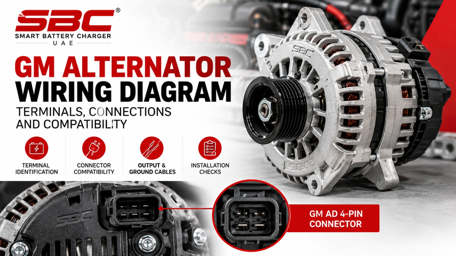
A GM alternator wiring diagram helps identify the main charging output, regulator or control connector, and the connections required for the alternator to work correctly with the vehicle’s electrical system. However, General Motors has used multiple alternator families and charging strategies, so a wiring layout that suits one unit may not suit another.
Before disconnecting wires or ordering a replacement, identify the alternator family, vehicle year, engine and connector type. The right match helps reduce installation errors, avoids incompatible electrical connections and gives you greater confidence before purchasing a replacement or upgrading your charging system.
Before You Use a GM Alternator Wiring Diagram
- Identify the alternator part number and family.
- Confirm the vehicle year, engine and electrical-system voltage.
- Match the connector and terminal identification to the correct documentation.
- Check the output cable, ground path and regulator or control requirements.
Need to identify an appropriate alternator application? Browse the Smart Battery Charger UAE product catalogue and verify fitment before ordering.
1. Identify the GM Alternator Before Wiring
Start with the alternator identification label, part number, mounting configuration and connector design. GM vehicles can use different alternator designs across model years and engine families. Two units that look similar externally may have different regulator arrangements or terminal assignments.
Some commonly encountered GM alternator families include AD244 and DR44 variants. These names alone are not enough to establish exact wiring compatibility. Confirm the complete part number and the specific vehicle application before following a diagram.
Use the SBC product catalogue to explore available alternator applications. Check the individual product documentation or contact the supplier when the vehicle and alternator details do not clearly match.
2. Understand the Main Alternator Connections
Alternator wiring commonly includes a high-current charging connection and one or more smaller connections used for sensing, warning indications or regulator control. The arrangement depends on the alternator design and vehicle electrical system.
| Connection area | Purpose | What to verify |
|---|---|---|
| Main output terminal | Carries charging current into the vehicle’s electrical system. | Terminal identification, cable capacity, routing and specified protection. |
| Regulator or control connector | May support voltage sensing, warning signals or regulator and vehicle-control functions. | Exact connector pinout and function for the specific alternator. |
| Ground path | Provides the required electrical return path through the designed grounding arrangement. | Mounting surfaces, ground cables and vehicle manufacturer requirements. |
Important: Do not assume that a terminal marked with a familiar letter has the same function on every GM alternator. Connector layouts and terminal functions vary by model. Never apply battery voltage or ground to an unidentified pin.
3. Check Connector Compatibility Before Buying
A connector that physically fits does not automatically mean that the alternator is electrically compatible. The regulator design, control requirements, terminal assignments and vehicle application must also match.
Use this compatibility checklist
- Vehicle: Record the make, model, year and engine.
- Alternator: Record the full part number and family designation.
- Connector: Compare the connector shape, pin count and documented terminal layout.
- Control strategy: Determine whether the system uses conventional regulator wiring or vehicle-computer control.
- Output requirement: Check the required charging capacity against the actual application and operating conditions.
- Installation: Confirm mounting, pulley, belt alignment, cable capacity and grounding requirements.
These checks are especially important when replacing a factory alternator with a higher-output unit. Confirming compatibility before purchase is generally more reliable than trying to resolve an electrical mismatch after installation.
4. Check Output Cable and Ground Capacity
The alternator output cable and ground path must be suitable for the expected current. A higher-output alternator does not automatically make the existing vehicle wiring suitable for the new installation.
Assess cable size using the expected current, cable length, routing, allowable voltage drop and applicable manufacturer instructions. Also verify suitable insulation, secure connections and overcurrent protection where required by the system design.
Use the SBC 12-volt wire-sizing chart as a reference for applicable 12V installations. Do not use a 12V chart as the sole sizing authority for a different system voltage or installation configuration.
For installation documents and additional technical resources, visit SBC Support.
5. Follow a Safe Wiring Verification Process
- Follow the vehicle manufacturer’s procedure for switching off the system and isolating the battery before working on charging-system wiring.
- Identify the alternator using its part number and obtain the matching vehicle or manufacturer wiring diagram.
- Compare the output terminal, connector pinout, regulator design and grounding arrangement against the documented application.
- Check cable sizing, routing and required circuit protection for the actual installation.
- Secure and insulate connections, keeping cables away from hot surfaces, sharp edges and moving components.
- Reconnect the system and test charging operation according to the vehicle manufacturer’s procedure.
For general charging-system inspection principles, consult the Bosch Charging Systems technical reference. This is general technical material, not a substitute for the exact GM alternator terminal diagram.
6. Common GM Alternator Wiring Mistakes
Using a diagram for a different alternator family
A diagram for one alternator generation may not represent another model’s connector or regulator strategy. Verify the part number and application first.
Assuming the connector shape proves compatibility
Physical fit alone does not confirm pin functions, regulator compatibility or suitability for the vehicle’s control system.
Ignoring the output cable and ground path
Charging-system performance depends on the complete electrical circuit, not only the alternator itself. Assess the positive cable and grounding arrangement when changing alternator output capacity.
Guessing the function of an unidentified terminal
Incorrect connections can cause component damage, charging faults or wiring problems. Stop and obtain the correct documentation if a terminal cannot be identified confidently.
7. When to Get Professional Help
Consult a qualified automotive electrician if the connector has been modified, the vehicle uses computer-controlled charging, wiring shows signs of overheating, or the correct terminal functions cannot be verified.
Professional verification is particularly valuable when adapting an alternator to a different application or upgrading the charging system beyond its original configuration.
Frequently Asked Questions
Is one GM alternator wiring diagram suitable for all GM vehicles?
No. Alternator families, vehicle years, engine applications and charging-control strategies vary. Use documentation that matches the exact alternator and vehicle.
What does the main alternator output terminal do?
The main output terminal carries charging current into the vehicle’s electrical system. Its cable, connections and circuit protection must meet the requirements of the specific installation.
Can I wire a GM alternator using the connector shape alone?
No. A similar-looking connector does not establish that the pin assignments, regulator design or electrical requirements are compatible.
Do I need to upgrade cables for a high-output alternator?
Not in every application, but the positive cable and ground path must be suitable for the expected current and installation. Check the applicable wiring guidance and manufacturer requirements before upgrading.
Can incorrect alternator wiring cause damage?
Yes. Incorrect connections, short circuits or incompatible control wiring can damage charging-system components. Verify terminal functions before powering the system.
Where can I find alternator products and installation resources?
Visit the Smart Battery Charger UAE product catalogue to review available applications and the support library for technical resources. Confirm exact fitment with the relevant product documentation before ordering.
Need Help Identifying the Right Alternator?
Before selecting a GM alternator or planning a higher-output upgrade, verify your vehicle details, alternator part number, connector type and electrical requirements.
Explore available applications in the Smart Battery Charger UAE product catalogue or review the technical support resources before making a purchase decision.